
Electrical pitting in bearings is an early-stage form of electrical discharge damage that appears as small crater-like depressions on the raceways and rolling elements. It is especially common in motors driven by variable frequency drives (VFDs), where shaft voltage and high-frequency currents stress the lubricant film and bearing surfaces. For engineers and maintenance personnel, correctly identifying electrical pitting—and distinguishing it from purely mechanical wear—is critical to preventing more advanced failures like frosting and fluting.
Throughout this article, you’ll discover:
- The basic definition of bearing pitting and how it presents on raceways
- Key differences between electrical pitting, mechanical pitting, frosting, and fluting
- The electrical mechanisms that cause pitting in VFD-driven motor bearings
- Practical methods to identify electrical pitting using visual, vibration, and lubricant clues
- How electrical pitting progresses into more severe EDM damage if left unchecked
- Effective prevention strategies, including grounding, insulation, and filtering
- Clear answers to common engineering questions about electrical pitting in the field
Let’s begin by defining what bearing pitting is and how electrical pitting fits into the broader spectrum of bearing damage.
What Is Bearing Pitting?
Definition: small crater-like depressions caused by material removal
Bearing pitting refers to localized material loss that appears as small, crater-like depressions on the raceway or rolling element surfaces. These pits form when the surface is overstressed—either mechanically or electrically—and small volumes of material are removed from the contact zone.
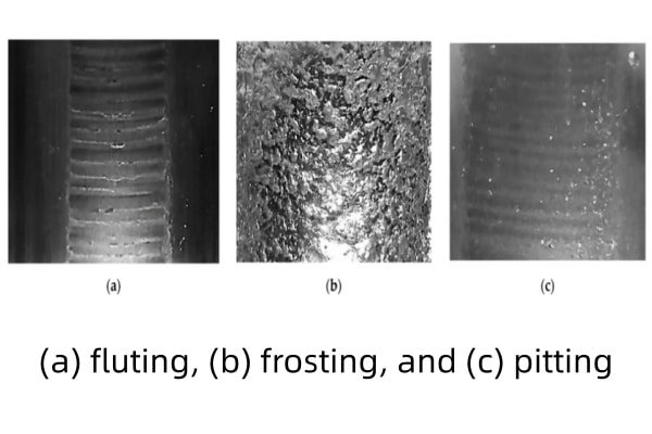
Difference between pitting, frosting, and early-stage fluting
Pitting consists of distinct, individual craters. Frosting is a dense field of fine micro-pits that creates a matte or gray, frosted appearance. Early-stage fluting starts as pitting that begins to align into faint, repeating bands; if the electrical stress continues, these bands develop into the characteristic washboard pattern of full fluting.
Why pitting is often the first visible sign of electrical discharge
Electrical discharge machining (EDM) events initially occur as sporadic arcs across the lubricant film. Each micro-arc removes a tiny volume of steel, forming a pit. Because these events begin long before serious mechanical symptoms appear, pitting is usually the first visible indicator that electrical discharge damage is occurring inside the bearing.
Electrical vs Mechanical Pitting
How electrical pitting forms (EDM micro-arcs, lubricant film breakdown)
Electrical pitting occurs when shaft voltage rises high enough to break down the lubricant film between rolling elements and raceways. At that point, a micro-arc jumps the gap, generating intense localized heat. The surface briefly melts and rapidly resolidifies, leaving behind a small crater or pit.
Mechanical fatigue pitting due to load, contamination, and misalignment
Mechanical pitting is driven by Hertzian contact stresses and surface fatigue. Excessive load, debris contamination, insufficient lubrication, or shaft misalignment can all cause repetitive overloading of the same area. Over time, fatigue cracks form below the surface, propagate, and release small fragments, leaving pits where material has broken away.
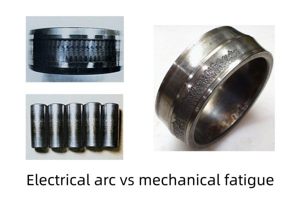
Visual pattern differences: crater edges, texture, density
Electrical pitting tends to produce sharp-edged, often circular craters with evidence of melting or discoloration around the pit. Mechanical pitting usually appears more irregular in shape, often distributed along the loaded zone and aligned with load direction. Electrical pitting may be clustered where discharge events are concentrated, while mechanical pitting typically follows the main contact track.
How to determine root cause using operating conditions and symptoms
Root cause assessment should combine visual evidence with operating context. Pitting in VFD-driven motors, especially where shaft voltage and poor grounding are present, strongly suggests electrical origin. Pitting in heavily loaded, dirty, or misaligned applications without VFDs is more likely mechanical. Vibration signatures, lubricant condition, and electrical measurements can further confirm the diagnosis.
Causes of Electrical Pitting in Bearings
Shaft voltage from PWM VFDs and common-mode voltage
PWM-based VFDs generate high-frequency common-mode voltage that capacitively couples to the rotor, creating shaft voltage. When this voltage cannot discharge safely through a low-impedance path, it builds up across the bearing lubricant film and causes EDM micro-arcs.
Capacitive discharge currents between stator and rotor
The stator–rotor airgap forms a parasitic capacitor. High-frequency voltage components charge this capacitance, and the stored energy discharges through bearings or other unintended paths, producing electrical pitting where the discharge occurs.
Circulating currents in large motors
In medium and large-frame motors, magnetic asymmetry and rotor geometry can induce circulating currents. These currents flow through both bearings unless one side is electrically insulated, increasing the risk of electrical pitting at the contact surfaces.
Insufficient grounding or improper cable installation
Poorly designed or installed grounding systems raise the impedance of safe return paths for high-frequency currents. Incorrect cable shielding, long cable runs, and improper bonding increase common-mode voltage and push more energy through the bearings, promoting pitting.
Weak dielectric strength of lubricant film under high-frequency stress
Every lubricant has a finite dielectric strength. High dv/dt switching, elevated temperatures, contamination, or aging can reduce that strength, making it easier for shaft voltage to puncture the film. Once the film breaks down, EDM arcs occur and electrical pitting begins.
Identification Methods
Visual inspection clues (micropits, arc marks, crater clusters)
Electrical pitting is typically identified under magnification. Look for clusters of small, round or slightly oval pits, sometimes with darkened or heat-tinted edges. Arc “burn” marks or melted zones around pits strongly suggest electrical activity rather than pure mechanical fatigue.
Vibration and noise signatures associated with early pitting
In early stages, electrical pitting may have only subtle effects on vibration. As pitting density grows, vibration levels increase at ball-pass frequencies, and noise may change from smooth operation to a faint hiss or roughness. Advanced stages may begin to resemble fluting-type vibration signatures.
Lubricant analysis for electrical degradation byproducts
EDM events generate localized high temperatures that can thermally degrade the grease or oil. Lubricant analysis may show increased oxidation products, darkening of the lubricant, or signs of burned additives, supporting the conclusion that electrical events are occurring in the bearing.
Electrical testing: hipot tests, dielectric tests, insulation checks
Electrical tests on the motor and drive system help confirm the presence of harmful voltages. Insulation resistance tests, hipot tests, and dielectric measurements across insulated components can validate whether intended barriers are effective or compromised. Elevated shaft-to-frame voltage measured with an oscilloscope is a direct indicator of risk.
When to disassemble vs when to monitor with condition-based tools
If vibration, noise, and electrical measurements indicate early damage but the motor is critical to production, it may be preferable to monitor closely with condition-based tools until a planned outage. Clear evidence of advanced pitting or rapid trend worsening is a strong trigger to schedule disassembly and bearing replacement.
Progression of Electrical Damage (Pitting → Frosting → Fluting)
How repeated EDM events evolve into patterned fluting
If electrical pitting is not addressed, EDM events continue and become more frequent. The pit density increases, transitioning into a frosted surface where individual pits are hard to distinguish. As the rolling elements repeatedly pass over the same points, wear becomes organized into bands, eventually producing the fluted, washboard-like pattern associated with severe electrical damage.
Early detection importance to avoid catastrophic bearing failure
Detecting pitting at an early stage allows corrective action—such as adding shaft grounding or upgrading to insulated bearings—before the bearing loses significant life. Once fluting develops, failure acceleration is rapid, and unplanned downtime becomes much more likely.
Prevention Methods
Shaft grounding rings or brushes
Shaft grounding devices provide a controlled, low-impedance path for shaft voltage to discharge safely to ground. By diverting current away from the bearing contacts, they dramatically reduce the likelihood of electrical pitting.
Insulated bearings or hybrid ceramic bearings
Coated bearings and hybrid ceramic bearings introduce a dielectric barrier into the current path. They are especially effective for breaking circulating current loops in larger motors and for protecting one end of the motor shaft from electrical discharge damage.
Increasing insulation thickness and verifying dielectric strength
For insulated bearings and components, sufficient coating thickness and verified dielectric strength are essential. Engineering specifications should define minimum breakdown voltage ratings appropriate to the drive system’s operating conditions.
Filters (dv/dt, sine-wave, common-mode chokes) to reduce harmful currents
Output filters on the VFD reduce common-mode voltage, dv/dt, and high-frequency components that drive shaft voltage and parasitic currents. These devices address the problem at its source and are particularly important on long-cable or high-voltage installations.
Ensuring proper grounding, bonding, and cable shielding
Good installation practice is fundamental: low-impedance ground paths, correct shield termination at both ends where appropriate, and compliant bonding practices minimize stray currents and reduce stress on bearings.
Maintenance intervals & inspection recommendations
Routine vibration monitoring, periodic shaft-voltage checks on critical motors, and planned inspection of bearings during overhauls form a complete strategy. When systems are upgraded to VFD control, additional early-life checks help confirm that mitigation is effective.
Frequently Asked Questions (FAQ)
What causes electrical pitting to start in the first place?
Electrical pitting begins when shaft voltage and common-mode voltage from the drive system exceed the lubricant film’s dielectric strength, causing micro-arcs across the bearing contact surfaces.
Can pitting be repaired, or does the bearing need replacement?
Pitting is not repairable in a practical way. Once electrical pitting is confirmed, the affected bearing should be replaced and the underlying electrical cause addressed.
How can I tell electrical pitting from normal wear?
Electrical pitting typically shows sharp, crater-like features with evidence of melting or discoloration and often coincides with VFD use or shaft voltage issues. Normal mechanical wear tends to be smoother, more uniform, and aligned primarily with load direction.
Does electrical pitting always lead to fluting?
If electrical stress remains and no mitigation is implemented, pitting commonly progresses through frosting to fluting. If corrective measures are taken early, it is possible to prevent fluting in new or replacement bearings.
Which motors are most at risk of electrical pitting?
Motors driven by PWM VFDs, especially larger-frame or high-voltage machines with long cable runs, poor grounding, or no shaft grounding/insulation, are at the highest risk of electrical pitting and related EDM damage.