
Variable Frequency Drives (VFDs) have revolutionized industrial motor control, offering unparalleled energy efficiency and precise speed regulation. However, this technological advancement comes with a hidden cost: a significant increase in premature bearing failures. For plant managers and reliability engineers, the sudden onset of noise and vibration in relatively new VFD-driven motors is a frustrating and expensive reality. The culprit is often not mechanical load, but invisible electrical currents generated by the drive itself.
In this technical analysis, you will explore:
- The fundamental conflict between VFD energy efficiency and bearing reliability.
- How Pulse Width Modulation (PWM) creates destructive Common Mode Voltage.
- The concept of parasitic capacitance and how motors act as capacitors.
- The process of Electrical Discharge Machining (EDM) that pits and flutes steel.
- Proven engineering solutions, from insulated bearings to shaft grounding rings, to protect your assets.
Let’s analyze how this energy-saving technology inadvertently creates a destructive force inside your motor.
The VFD Paradox: Energy Efficiency vs. Bearing Reliability
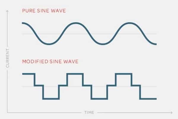
VFDs control the speed of AC induction motors by adjusting the frequency and voltage of the power supplied to the motor. While this optimizes process control and reduces electricity consumption, it fundamentally changes the quality of power the motor receives. Unlike the clean, balanced sine wave of standard line power, VFDs output a simulated waveform. This simulation is the root cause of electrical bearing damage.
The Physics: How VFDs Create Shaft Voltages
To understand why bearings fail, we must look at the switching mechanism inside the drive.
Pulse Width Modulation (PWM) Explained Simply
VFDs use a technique called Pulse Width Modulation (PWM). The drive’s rectifiers convert AC power to DC, and then high-speed transistors (IGBTs) switch the DC voltage on and off thousands of times per second to simulate an AC sine wave. While effective for torque control, this rapid switching creates steep voltage wavefronts (high dV/dt), resulting in high-frequency electrical noise.
Common Mode Voltage: The Real Culprit
In a standard three-phase power supply, the sum of the three phases is always zero. However, due to the nature of PWM switching, the three phases do not sum to zero at any given instant. This imbalance creates a “Common Mode Voltage” on the motor windings. This non-zero voltage seeks a path to the earth ground to neutralize itself.
Parasitic Capacitance: The Motor as a Capacitor
A motor is not just an inductive load; it also contains parasitic capacitance. The stator windings and the rotor act as two plates of a capacitor, with the air gap serving as the dielectric. Through capacitive coupling, the high-frequency common-mode voltage from the stator is induced onto the rotor shaft. The shaft is now electrically charged, sitting on isolated bearings, looking for a way to ground.
From Voltage to Damage: The EDM Process
The shaft voltage itself is not the problem; the discharge is.
Breaking the Dielectric Strength
Bearings contain a thin film of lubricating grease that separates the rolling elements from the raceways. This grease acts as an electrical insulator (dielectric). As the shaft voltage rises, it eventually exceeds the dielectric strength of the grease film. This threshold varies but is typically between 10 and 30 volts.
The “Spark”: Electrical Discharge Machining (EDM)
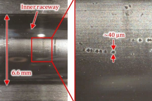
When the voltage breaks through the grease film, an instantaneous arc occurs. This phenomenon is known as Electrical Discharge Machining (EDM). The current discharges through the bearing to the grounded motor frame. This arc generates intense localized heat (approaching 4,000°C), melting a tiny pit in the steel raceway and fusing the metal. Over time, millions of these micro-discharges create frosting, pitting, and eventually, the rhythmic “fluting” pattern that destroys the bearing.
Factors That Increase VFD Bearing Damage Risks
Certain operational parameters can exacerbate the severity of electrical erosion.
- Carrier Frequency: Higher switching frequencies (carrier frequencies) improve waveform smoothness but increase the rate of capacitive coupling, leading to more frequent discharges.
- Poor Cabling: Using unshielded motor cables allows high-frequency noise to radiate and prevents currents from returning safely to the drive, forcing them through the motor structure.
- Improper Grounding: If the motor frame is not bonded to a low-impedance ground, the shaft voltage has nowhere to go but through the driven equipment or the bearings.
Proven Solutions for VFD Motor Protection
Understanding the cause allows for the selection of appropriate mitigation products. There are two primary strategies: blocking the current or diverting it.
Insulated Bearings: Blocking the Path
Insulated bearings are designed to interrupt the circuit.
- Hybrid Ceramic Bearings: These replace steel balls with Silicon Nitride (ceramic) rolling elements. Ceramic is non-conductive, offering the highest level of protection against current passage. They are ideal for critical applications.
- Coated Bearings: These feature an insulating oxide layer on the outer or inner ring. They are a cost-effective alternative for larger motors.
Shaft Grounding Rings (SGR): Diverting the Current
Instead of stopping the current, Shaft Grounding Rings (SGR) provide a low-resistance path for the current to bypass the bearings. These rings use conductive micro-fibers or carbon brushes to bleed the shaft voltage safely to the grounded motor frame. They are commonly installed on the drive end of the motor.
Inductive Absorbers (Common Mode Chokes)
Installed on the output cables of the VFD, these magnetic cores (such as CoolBLUE cores) absorb the high-frequency noise before it reaches the motor, reducing the magnitude of the common-mode voltage at the source.
Which Solution is Best?
For motors under 100 HP, a shaft grounding ring is often the most cost-effective retrofit. For larger motors (over 100 HP) or critical applications, a combination of an insulated bearing on the non-drive end and a grounding ring on the drive end is the gold standard for protection.
Frequently Asked Questions (FAQ)
Do all VFD motors need insulated bearings?
Not always. Small motors (under 10 HP) may be less susceptible, but the risk exists for any VFD-driven motor. For critical process motors, protection is highly recommended regardless of size.
How do I measure common mode voltage?
You cannot use a standard multimeter. Measuring shaft voltage requires an oscilloscope with a special shaft grounding brush probe to detect the high-frequency voltage spikes.
Can I just use standard grease for VFD motors?
Standard grease is not conductive enough to bleed charge, nor insulating enough to stop it. Conductive greases exist but have shorter lifespans. The mechanical/electrical solution (grounding rings or insulated bearings) is preferred over chemical solutions.