
In the era of variable frequency drives (VFDs), identifying the root cause of bearing failure has become more complex. What appears to be a mechanical lubrication issue may actually be a symptom of stray electrical currents destroying your motor from the inside out. For maintenance teams, distinguishing between mechanical wear and electrical erosion (EDM) is critical—mistaking one for the other often leads to repeat failures and wasted budget.
This diagnostic guide will equip you with the knowledge to:
- Visually identify the “washboard” fluting pattern and electrical pitting on raceways.
- Distinguish electrical damage from mechanical false brinelling or corrosion.
- Use an oscilloscope and shaft grounding probe to scientifically measure damaging voltages.
- Analyze bearing grease for signs of electrical carbonization (“burnt” grease).
- Understand the specific auditory signatures of electrically damaged bearings.
Let’s start with the most immediate method of diagnosis: looking at the physical evidence.
1. Visual Inspection: Recognizing the Physical Signs
Most electrical damage is identified during a teardown analysis. The damage leaves distinct signatures on the bearing surfaces that differ from fatigue or load-related failure.
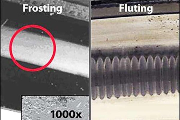
Fluting (The Washboard Pattern)
The most unmistakable sign of advanced electrical damage is “fluting.” This manifests as a pattern of evenly spaced, parallel lines across the width of the bearing raceway. It resembles the texture of a washboard. These grooves are carved by the rhythmic vibration of the rolling elements as they pass over thousands of microscopic electrical pits.
Electrical Pitting (Micro-Cratering)
Before fluting appears, the damage starts as pitting. To the naked eye, this looks like a frosted, dull gray band on the raceway or the rolling elements. Under a microscope, you would see thousands of tiny craters where the steel has been melted by electrical arcs. This “frosting” is often the first visual warning sign.
Discoloration of Rolling Elements
In severe cases, the balls or rollers themselves will lose their shiny, polished finish. They often take on a dull, gun-metal gray appearance due to the constant micro-arcing and surface degradation.
Grease Analysis: The “Burnt” Look
Electrical arcing generates intense localized heat, which chemically breaks down the lubricant. If you open a bearing and the grease is blackened, hardened, or smells distinctly burnt (not just old), it is a strong indicator of current passage. This carbonized grease loses its lubricating properties, accelerating mechanical wear.
2. Auditory & Vibration Analysis: Listening for the Problem
You don’t always need to disassemble the motor to suspect electrical damage.
The Characteristic Sound
Electrically damaged bearings produce a unique noise profile. As the fluting pattern develops, the motor will emit a loud, high-pitched whining, whistling, or screeching sound. This noise typically varies directly with motor speed and is distinct from the low-frequency grinding or rumbling associated with standard mechanical spalling.
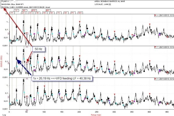
Vibration Spectrum Analysis
Vibration analysis can confirm the issue. While standard bearing defects show peaks at BPFO (Ball Pass Frequency Outer) or BPFI (Inner), electrical fluting often generates a “haystack” pattern in the high-frequency range or distinct sidebands around the bearing defect frequencies, indicating the rhythmic nature of the washboard surface.
3. Shaft Voltage Measurement: The Definitive Test
Visual inspection confirms damage after it happens. Shaft voltage testing confirms the risk before failure occurs.
Why a Standard Multimeter Is Not Enough
Do not use a standard digital multimeter (DMM) to test for VFD-induced shaft voltages. VFDs switch at high frequencies (kHz to MHz range). A standard DMM averages these signals and will show a misleadingly low voltage (often near zero). You need an instrument capable of capturing high-speed transients.
Tools Needed
To perform this test accurately, you need:
- A portable oscilloscope (min 100 MHz bandwidth recommended).
- A shaft voltage probe tip: This is a special probe with a conductive carbon brush or microfiber tip that rides on the spinning shaft to pick up the voltage.
Step-by-Step Testing Procedure
- Safety First: Ensure all safety protocols are followed for working near rotating machinery.
- Ground the Scope: Connect the oscilloscope’s ground lead securely to the unpainted metal of the motor frame.
- Contact the Shaft: Gently press the carbon brush probe against the center of the rotating motor shaft end. Ensure good contact.
- Adjust Settings: Set the time base to view the PWM pulses (often around 50-100 microseconds/div).
- Capture: Look for vertical voltage spikes.
Interpreting the Results
A “safe” motor typically shows shaft voltages below 5-10 volts peak-to-peak. If you see frequent spikes exceeding 10-20 volts (or higher, depending on the motor size and grease type), the dielectric strength of the grease is likely being exceeded, causing discharge (EDM) inside the bearing.
Distinguishing Electrical Damage from Mechanical Failure
Misdiagnosis is common. Here is how to tell the difference.
Electrical Fluting vs. False Brinelling
Both look like grooves.
- False Brinelling: Caused by vibration when the motor is stopped (e.g., during shipping). The marks are spaced at the exact distance of the rolling elements and often have the original grinding marks visible at the bottom. They may be reddish due to fretting corrosion.
- Electrical Fluting: Caused while running. The grooves are typically closer together than the ball spacing and the bottom of the groove is melted or shiny, not abraded.
Electrical Pitting vs. Chemical Corrosion
Corrosion (rust) is irregular and often widespread on all exposed surfaces. Electrical pitting is confined strictly to the “load zone” or the contact path of the rolling elements where the arc bridges the gap.
Common Causes & Quick Fixes
If you confirm electrical damage, the root cause is almost always the VFD system.
- Improper Grounding: Ensure the motor frame is bonded to the facility ground with a low-impedance strap.
- Unshielded Cables: Replace standard wiring with shielded VFD cables to reduce common-mode noise.
- No Protection: Install a Shaft Grounding Ring (SGR) on the drive end to bleed voltage, or replace the bearings with Insulated (Ceramic) Bearings to block the current.
Frequently Asked Questions (FAQ)
Can I test for EDM damage without stopping the motor?
Yes, using the shaft voltage measurement method described above (oscilloscope + probe) allows you to diagnose the risk while the motor is running. Vibration analysis can also be done live.
How fast does electrical erosion destroy a bearing?
It varies, but in aggressive VFD applications without protection, significant damage can occur in as little as 3 months to a year. Some motors fail within weeks if the shaft voltage is exceptionally high.
What does the “tiger stripe” pattern indicate?
“Tiger striping” is another term for fluting. It indicates that the bearing has been subjected to prolonged electrical arcing, causing the rolling elements to bounce rhythmically and carve grooves into the race.