
The widespread adoption of Pulse Width Modulation (PWM) Variable Frequency Drives (VFDs) has revolutionized motor control efficiency but introduced a complex parasitic phenomenon: high-frequency bearing currents. Unlike traditional line-frequency sinusoidal power, VFDs generate high-frequency voltage pulses that create stray capacitive and inductive paths within the motor. For electrical engineers and reliability specialists, understanding these currents is not just academic—it is essential for protecting large capital assets from rapid, unexplained failure.
In this technical analysis, you will examine:
- The physics of parasitic capacitance and how VFD switching creates common mode voltage.
- The critical distinction between capacitive EDM currents and high-frequency circulating currents.
- Why large motors (>100 HP) are uniquely susceptible to inductive loop currents.
- The “skin effect” and why standard grounding wires fail at high frequencies.
- Targeted mitigation strategies, including proper bonding, grounding rings, and insulated bearings.
Let’s analyze the invisible electrical forces at play inside your motor housing.
The Physics of High-Frequency Currents (Technical Basics)
To understand bearing currents, one must view the AC induction motor not just as a magnetic machine, but as a complex network of high-frequency parasitic capacitors.
How VFDs Generate High-Frequency Noise
Modern VFDs use Insulated Gate Bipolar Transistors (IGBTs) to switch DC bus voltage on and off at frequencies ranging from 2 kHz to 20 kHz. This rapid switching creates voltage pulses with very fast rise times (high dV/dt). These steep wavefronts contain high-frequency harmonic content that behaves differently than standard 50/60 Hz power.
The Concept of Common Mode Voltage
In a balanced three-phase sine wave system, the vector sum of voltages is zero. However, in a PWM drive, the three phases never sum to zero instantaneously. This results in a non-zero Common Mode Voltage relative to the earth ground. This voltage appears on the stator windings and looks for a path to ground.
Parasitic Capacitance: The Motor as a Capacitor
Due to the close proximity of internal components, stray capacitance exists:
- Stator-to-Rotor Capacitance (Csr): The air gap acts as a dielectric. The common mode voltage charges the rotor shaft through this capacitance (Capacitive Coupling).
- Rotor-to-Ground Capacitance (Crg): The bearings themselves act as capacitors, with the oil film forming the dielectric layer between the inner and outer races.
Types of High-Frequency Bearing Currents
Not all bearing currents are the same. Distinguishing between them is vital for selecting the correct mitigation strategy.
1. Capacitive Discharge Currents (EDM)
This is the dominant failure mode in smaller motors. The rotor shaft accumulates voltage via capacitive coupling. When this voltage exceeds the dielectric breakdown threshold of the bearing grease (typically 10-30V), the energy discharges instantaneously through the rolling element. This spark is known as Electrical Discharge Machining (EDM).
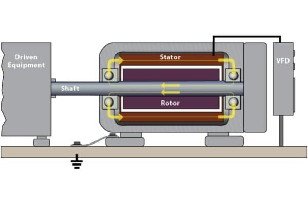
2. High-Frequency Circulating Currents
This type is prevalent in larger motors (typically above 100 HP / 75 kW). The high-frequency flux circulating in the stator creates a magnetic imbalance. This high-frequency flux links the stator frame and the rotor, inducing a voltage along the shaft length. This creates a loop: current flows down the shaft, through the drive-end bearing, through the motor frame, and back up through the non-drive-end bearing. This continuous “circulating” current destroys both bearings simultaneously.
3. Rotor Ground Currents
If the motor frame is poorly grounded but the driven load (e.g., pump or fan) is well grounded, current will flow from the shaft, through the coupling, and into the load’s bearings to find earth ground. This can damage the gearbox or pump bearings instead of the motor bearings.
The Damage Mechanism: What HF Currents Do to Steel
Regardless of the current type, the physical damage mechanism is thermal.
Breakdown of the Lubrication Film
The bearing’s lifeblood is its elastohydrodynamic (EHD) lubrication film. High-frequency discharges puncture this film. The heat vaporizes the oil’s additives and base stock, leading to “black grease” syndrome—carbonization that destroys lubricity.
Micro-Welding and Cratering
Each discharge melts a microscopic pit (crater) in the steel. The material is heated to its melting point and then rapidly quenched by the surrounding metal, creating hard, brittle martensite structures that are prone to cracking.
Frosting vs. Fluting
Frosting: The early stage, appearing as a dull, gray, sandblasted band.
Fluting: The advanced stage, where rhythmic vibrations organize the pits into deep, parallel washboard grooves. This is the definitive sign of VFD-induced failure.
Mitigation Strategies: Breaking the Path
The goal is to either provide a safe path to ground or block the current flow entirely.
High-Frequency Bonding
Standard round copper ground wires have high impedance at high frequencies due to the “skin effect” (current flows only on the outer surface). To effectively ground VFD motors, you must use flat, braided grounding straps. These provide a large surface area, offering low impedance for high-frequency noise to return to the source.
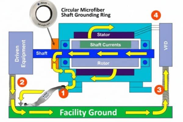
Shaft Grounding Rings (For EDM Currents)
For capacitive EDM currents, a Shaft Grounding Ring (SGR) is effective. It provides a low-resistance path from shaft to frame, bleeding off the voltage before it builds up enough to arc through the bearing.
Insulated Bearings (For Circulating Currents)
For large motors suffering from circulating currents, grounding rings alone may not suffice. The loop must be broken. Installing an Insulated Bearing (ceramic coated or hybrid) on the Non-Drive End (NDE) breaks the electrical circuit, preventing current from circulating through the frame.
Inductive Absorbers (Common Mode Chokes)
Installing inductive absorption cores (like CoolBLUE) on the VFD output cables helps dampen the high-frequency noise and reduce common mode voltage at the source, treating the disease rather than just the symptoms.
Frequently Asked Questions (FAQ)
At what motor size do circulating currents become a problem?
While there is no hard cutoff, the risk increases significantly for motors above 100 HP (75 kW) due to larger physical dimensions increasing the magnetic asymmetry and parasitic capacitance.
Can dV/dt filters prevent high-frequency bearing currents?
They help reduce the steepness of the voltage rise, which lowers the magnitude of capacitive coupling, but they typically do not eliminate common mode voltage entirely. They are often part of a broader solution.
Why doesn’t a standard multimeter detect high-frequency voltage?
Standard multimeters are designed for 50/60 Hz. They cannot sample fast enough to capture the microsecond-level voltage spikes of PWM switching. You need an oscilloscope with at least 100 MHz bandwidth.
一条评论
Pingback: Can a Standard Bearing Be Replaced With an Insulated One?