
When specifying an electrically insulated bearing, “more” isn’t always better—but “enough” is critical. The thickness of the ceramic coating (typically Aluminum Oxide) is the primary variable that determines the bearing’s ability to withstand shaft voltages. However, increasing this thickness introduces mechanical and thermal trade-offs. For electrical and reliability engineers, understanding the physics behind coating depth—specifically its relationship to breakdown voltage and capacitance—is essential for selecting the right component for VFD motors and generators.
In this technical analysis, you will examine:
- The direct correlation between coating thickness and DC breakdown voltage.
- How increasing thickness reduces parasitic capacitance (Impedance physics).
- The mechanical limits: Why coatings rarely exceed 300-500µm.
- Thermal conductivity concerns: Does thick insulation overheat the bearing?
- Industry standards for Standard vs. Enhanced insulation layers.
Let’s measure the impact of every micron.
The Physics: How Thickness Defines Electrical Performance
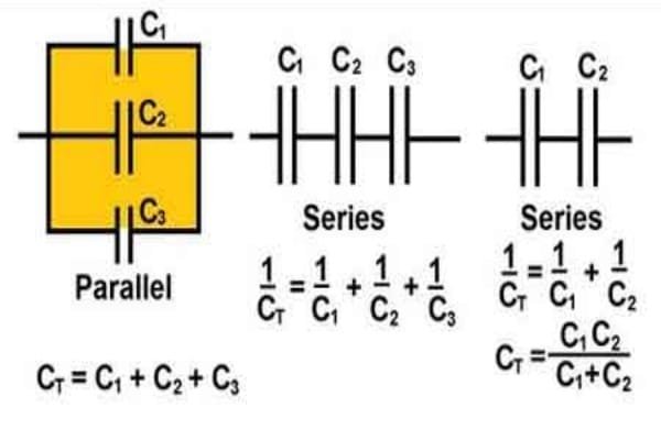
The insulation layer functions as the dielectric in a capacitor. Its geometry dictates its electrical properties.
Breakdown Voltage: The Linear Relationship
Dielectric strength is roughly linear. The thicker the wall, the more voltage it takes to punch through.
Standard Data:
• ~100µm (0.1mm) coating typically withstands >1,000V DC.
• ~300µm (0.3mm) coating typically withstands >3,000V DC.
This is why high-voltage traction motors require the thicker “Enhanced” specification.
Capacitance Reduction: The Inverse Relationship
This is crucial for VFD applications. A coated bearing acts as a parallel plate capacitor. The capacitance (C) is inversely proportional to the thickness (d):
C = εA/d
The Implication: Doubling the coating thickness cuts the capacitance in half. Lower capacitance means higher impedance (Xc) to high-frequency AC currents. Therefore, thicker coatings are superior for blocking High-Frequency VFD noise, not just high DC voltage.
Ohmic Resistance
While breakdown voltage and capacitance depend on thickness, the basic DC Ohmic resistance (>50 MΩ) is achieved even with thin layers, provided they are properly sealed against moisture.
Typical Thickness Standards in the Industry
Manufacturers categorize their products based on these thickness tiers.
Standard Layer (<100µm)
Application: Low Voltage (<500V) industrial motors, pumps, fans.
Goal: Prevent standard EDM sparking. Cost-effective and minimal impact on dimensions.
Enhanced Layer (300µm+)
Application: Medium Voltage motors, Traction motors, Wind Generators.
Goal: Withstand high dV/dt spikes and voltages >1000V. Often marketed as “VL2071” or similar premium codes.
Hybrid Bearings: The “Infinite” Thickness
Comparison: A Hybrid bearing replaces the coating with a solid silicon nitride ball. The “insulation thickness” is effectively the diameter of the ball (e.g., 10mm-20mm). This provides vastly superior electrical isolation compared to any micron-scale coating.
The Trade-Offs: Can Insulation Be Too Thick?
Why don’t we just spray 1mm of ceramic on every bearing?
Thermal Conductivity Issues
Aluminum Oxide is a thermal insulator ($30 W/mK$) compared to bearing steel ($50 W/mK$), but significantly better than organic resin. However, as the coating gets thicker, it creates a thermal barrier.
Risk: An excessively thick coating (>500µm) could impede heat transfer from the outer ring to the housing, potentially causing the bearing to run hotter.
Mechanical Fragility
Plasma-sprayed ceramic has internal residual stresses. As the coating thickness increases, these stresses build up.
Engineering Limit: Coatings beyond 500µm are prone to delamination (peeling off) under thermal cycling or press-fit pressure. This is the practical limit of current plasma spray technology.
Dimensional Tolerances
The coating adds material. To maintain standard ISO bearing dimensions (Boundary Dimensions), the steel ring must be ground down (undercut) before coating. A very thick coating would require removing too much structural steel from the ring, potentially weakening it.
Quality Control: Measuring Thickness and Integrity
How do you verify the spec?
Non-Destructive Testing
Technicians use Magnetic Induction Gauges (Eddy Current) to measure the non-magnetic coating thickness over the magnetic steel substrate. This confirms the physical depth (e.g., is it truly 300µm?).
The Spark Test
Thickness means nothing if there is a pinhole. Manufacturers perform a 100% Spark Test, passing a high-voltage probe over the entire surface to detect any microscopic voids or porosity.
Frequently Asked Questions (FAQ)
Does thicker insulation last longer?
Electrically, yes—it provides a larger safety margin against voltage spikes. Mechanically, no—it has the same fatigue life as a standard bearing, provided the coating doesn’t crack.
Can I grind the coating down to fit a smaller housing?
Absolutely not. Grinding the coating reduces its thickness (lowering breakdown voltage) and can destroy the surface seal, making it vulnerable to moisture. Never modify the coated surface.
What is the minimum thickness for 690V VFD applications?
For 690V systems, the DC bus voltage can exceed 1000V. Therefore, a standard 100µm coating (rated 1000V) is borderline. It is safer to specify the Enhanced (300µm) coating or use Hybrid bearings.