
For an insulated bearing, the ceramic coating is its shield. However, a shield is useless if it falls off. In high-voltage motors and generators, the durability of the insulation layer—specifically its adhesion to the steel substrate—is just as critical as its dielectric strength. Engineers must understand that applying a ceramic layer to a steel ring involves overcoming significant physical challenges, including thermal expansion mismatch and residual stress. This guide delves into the materials science of adhesion, global testing standards like ASTM C633, and the failure modes that threaten coating integrity.
1. The Physics of Adhesion: How Coatings “Stick”
Ceramic (Aluminum Oxide) does not naturally bond to steel. There is no chemical reaction that fuses them together. Instead, the bond is primarily mechanical.
Mechanical Interlocking (The Primary Mechanism)
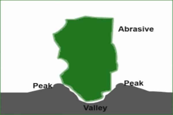
The foundation of coating adhesion is surface roughness.
Surface Preparation: Before coating, the bearing ring is grit-blasted with coarse aluminum oxide grit. This creates a jagged, cratered surface with a specific Roughness Average ($Ra$).
The “Anchor Pattern”: When the molten ceramic particles from the plasma spray hit this surface, they flow into the microscopic valleys and crevices before solidifying. As they cool and shrink, they physically lock onto the steel peaks. This “mechanical interlocking” provides 80-90% of the bond strength.
Residual Stress Management
Adhesion is a constant battle against stress.
Thermal Mismatch: Bearing steel expands at a rate of ~$12 \times 10^{-6}/K$. Aluminum Oxide expands at ~$8 \times 10^{-6}/K$. When the bearing heats up during operation, the steel wants to expand more than the coating. If the bond strength is lower than the shear stress generated by this mismatch, the coating will delaminate. Managing the cooling rate during the spray process is vital to keep these residual stresses within safe limits.
2. Factors Affecting Coating Durability
Why do some coatings last 20 years and others fail in 6 months?
Porosity and Sealing (Crucial)
Plasma-sprayed coatings are inherently porous (sponge-like structure).
The Sponge Effect: Without treatment, these pores are pathways for moisture.
Impregnation: High-quality bearings are vacuum-impregnated with a sealing resin (phenolic or epoxy). This resin not only blocks moisture but also acts as a “glue” within the ceramic matrix, improving the cohesive strength and toughness of the coating.
Coating Thickness Limitations
Thicker is not always better for durability.
The Thickness-Adhesion Trade-off: As coating thickness increases (e.g., >500µm), the internal residual stresses build up exponentially. A very thick coating is under high internal tension and is much more likely to crack or peel off (spall) under thermal shock or mechanical load.
3. Testing Standards: Quantifying Bond Strength
How do we measure “stickiness” in an engineering lab?
ASTM C633: Tensile Bond Strength Test
This is the global gold standard for thermal spray coatings.
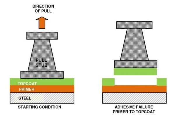
The Setup: A test stud is glued to the coated surface with extremely strong epoxy. The machine pulls the stud perpendicular to the surface until failure occurs.
Acceptance Criteria: For high-quality bearing insulation, the bond strength should typically exceed 40 MPa (5,800 psi). If the failure occurs in the glue instead of the coating, the bond strength is considered “greater than the glue strength.”
ISO 14923: Thermal Spraying Characterization
This standard guides the visual and metallographic inspection. Cross-section analysis under a microscope reveals the interface quality, checking for continuous contact between the steel and ceramic without large voids or oxidation layers.
4. Common Failure Modes: Why Coatings Fail
Recognizing the failure pattern helps identify the root cause.
Delamination (Separation at Interface)
Appearance: Large patches of coating peel off, revealing the bare steel underneath.
Root Cause: Poor surface preparation (oil or rust left on the steel before spraying) or extreme thermal shock.
Spalling (Chipping)
Appearance: Small chips missing from the edges or corners.
Root Cause: Mechanical impact. This is almost always caused by a technician hitting the bearing ring with a hammer or drift during installation.
Blistering (Subsurface Corrosion)
Appearance: Bubbles forming under the coating.
Root Cause: Sealing failure. Moisture penetrated the porous ceramic, causing the steel underneath to rust. The expanding rust (iron oxide) pushes the coating up, creating a blister.
5. Best Practices for Maximizing Durability
Engineers and technicians play a huge role in coating survival.
Installation & Handling
The “No Hammer” Rule: Ceramic is brittle. Never strike an insulated bearing. Use induction heaters to expand the inner ring for shaft mounting, or use a mechanical press that applies force only to the steel face.
Housing Fit Tolerance
Preventing Creep: If the coated outer ring spins inside the housing (creep), the abrasive ceramic will wear against the housing, or the friction will overheat and crack the coating. Adhere strictly to ISO tolerances (typically H7 or J7) to ensure a secure fit.
Frequently Asked Questions (FAQ)
What is the typical bond strength of INSOCOAT?
According to SKF technical data, standard INSOCOAT bearings exhibit a bond strength >40 MPa, ensuring the coating remains intact under normal press-fit pressures.
Can I re-coat a bearing if the insulation chips?
No. Re-coating requires stripping the old ceramic, re-blasting (which removes steel material and changes tolerances), and re-spraying. It is not economically feasible or technically sound to repair a damaged coating.
How does temperature affect coating adhesion?
Within the standard operating range (-40°C to +150°C), adhesion remains stable. However, rapid temperature changes (thermal shock) are more dangerous than high steady-state temperatures due to the expansion mismatch.