
Modern industrial automation is pushing the boundaries of speed and efficiency. The advent of High-Frequency Drives, particularly those utilizing Silicon Carbide (SiC) or Gallium Nitride (GaN) semiconductors, has enabled motors to operate at unprecedented switching frequencies. While this reduces audible noise and improves control, it introduces a severe threat to motor reliability: ultra-high-frequency shaft voltages. Standard bearing protection methods often fail in these environments. Understanding why high-frequency currents behave differently—and specifying the correct insulated bearings—is the only way to prevent rapid, catastrophic failure.
In this technical guide, you will examine:
- How high $dV/dt$ from fast-switching drives creates potent shaft voltages.
- The “Capacitor Effect”: Why standard insulated coatings can fail at high frequencies.
- Why Hybrid Ceramic bearings are the gold standard for SiC and GaN drive systems.
- The critical role of high-frequency bonding straps in grounding.
- Real-world applications from CNC spindles to EV test benches.
Let’s analyze the physics of keeping high-frequency noise out of your bearings.
How High-Frequency Drives Impact Motor Bearings
High-frequency drives are not just “faster” VFDs; they fundamentally change the electrical stress on the motor.
Understanding dV/dt and Switching Frequencies
Traditional IGBT-based drives switch in microseconds. New SiC-based drives switch in nanoseconds. This extremely fast rise time in voltage is known as high dV/dt. According to research from major drive manufacturers like ABB and Danfoss, this steep voltage wavefront significantly increases the magnitude of the Common Mode Voltage coupled to the motor shaft.
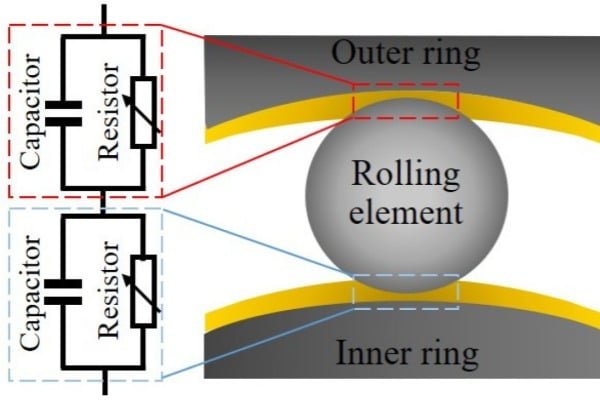
The Physics: Capacitive Coupling
At high frequencies, the impedance of the parasitic capacitance between the stator and rotor decreases ( Xc = 1 / (2πfC)). This means that as frequency (f) goes up, the motor becomes more conductive to stray currents. High-frequency drives essentially turn the motor’s air gap into a low-impedance path, flooding the rotor shaft with electrical potential.
Micro-Pitting Acceleration
Because the discharge rate is proportional to the switching frequency, a drive operating at 20 kHz generates thousands more discharge events per second than an older 4 kHz drive. This accelerates the “micro-pitting” process, turning a bearing into scrap metal in a fraction of the usual time.
The Limitation of Standard Insulated Bearings
Engineers often assume “any insulated bearing will do.” In high-frequency applications, this is a dangerous assumption.
The Capacitor Effect: Can Current Jump Across Coatings?
Standard coated bearings (like INSOCOAT) use a thin layer of aluminum oxide. While this layer is an insulator at DC or low frequencies, at very high frequencies, it acts as a dielectric in a capacitor.
The Risk: High-frequency currents can capacitively couple through the thin coating. While the coating prevents DC current flow, it may allow enough high-frequency AC energy to pass through to cause damage, especially if the coating is thin or porous.
Solutions: Selecting the Right Protection for HF Systems
For high-frequency systems, you need insulation with minimal capacitance and maximum impedance.
Hybrid Ceramic Bearings: The Gold Standard
Hybrid bearings (steel rings with silicon nitride balls) are superior because the ceramic rolling elements are physically thick insulators.
Why they work: The solid ceramic ball provides a massive dielectric barrier compared to a thin coating. This virtually eliminates parasitic capacitance, making them the only reliable choice for SiC-driven motors.
Grounding Solutions: High-Frequency Bonding
Insulation protects the bearing, but the noise must go somewhere. Standard round copper wire has high impedance at high frequencies due to the “skin effect.”
The Fix: Use High-Frequency Bonding Straps (flat, braided copper). The large surface area provides a low-impedance path for high-frequency noise to return to the drive chassis, rather than trying to jump through the motor bearings.
Inductive Absorbers (Common Mode Chokes)
Installing inductive cores (like CoolBLUE or Nanocrystalline cores) on the drive output cables is highly effective. These chokes absorb the high-frequency common mode noise before it even reaches the motor.
Real-World Application Cases
Where is this technology most critical?
High-Speed Spindle Motors
CNC machining centers use high-frequency drives to spin tools at 20,000+ RPM. The combination of high speed and high frequency makes hybrid bearings mandatory to prevent vibration marks on the machined parts.
EV Test Bench Dynos
Dynamometers used to test Electric Vehicle motors often use high-performance SiC drives to simulate driving conditions. These dynos rely on hybrid bearings to ensure that any failure detected is in the test part, not the dyno motor itself.
Frequently Asked Questions (FAQ)
Is INSOCOAT effective for Silicon Carbide (SiC) drives?
It provides some protection, but Hybrid Ceramic bearings are strongly recommended for SiC drives due to the potential for capacitive leakage through standard coatings at extreme switching speeds.
Do I need insulated bearings on both ends of the motor?
For high-frequency drives, yes. The potential for high-frequency circulating currents and shaft voltages is severe enough that total isolation (insulating both DE and NDE) is often the safest engineering choice.
What is the difference between VFD and HF Drive bearing issues?
It is a matter of intensity. HF drives generate higher shaft voltages and more frequent discharge events, causing damage much faster than standard VFDs if unprotected.