
The railway industry is relentless in its pursuit of efficiency and speed. The transition from DC traction to AC propulsion, powered by fast-switching IGBT and SiC inverters, has revolutionized locomotive performance. However, this technological leap has introduced a critical vulnerability: electrical bearing damage. Traction motors operate in one of the harshest electrical environments on earth, subject to massive shaft voltages and high-frequency currents. For railway engineers, adhering to standards like IEC 60349-2 is not just about compliance; it is about ensuring the safety and reliability of the rolling stock that moves the world.
In this railway engineering guide, you will learn:
- How modern AC traction inverters generate destructive common mode voltages.
- The difference between EDM currents and high-frequency circulating currents in rail motors.
- A technical comparison of Plasma-Sprayed (INSOCOAT) vs. Hybrid Ceramic bearings.
- Key international standards for traction motor insulation (IEC 60349-2 / IEEE).
- Maintenance strategies for testing insulation resistance in heavy-duty rail environments.
Let’s examine the technology keeping traction motors on track.
The Critical Role of Traction Motors in Modern Rail
Traction motors are the heart of electric locomotives, EMUs (Electric Multiple Units), and high-speed trains.
From DC to AC: The Inverter Revolution
Older DC traction motors had their issues, but bearing currents were rare. Modern AC asynchronous and permanent magnet motors are driven by Variable Voltage Variable Frequency (VVVF) inverters. These inverters use Pulse Width Modulation (PWM) to control torque and speed precisely. The side effect is the generation of high-frequency harmonics and steep voltage wavefronts (high dV/dt).
The Hidden Threat: Common Mode Voltage
Because the three-phase output of a traction inverter never sums to zero, a high-amplitude “Common Mode Voltage” exists on the motor windings relative to the bogie frame. This voltage capacitively couples to the rotor shaft. Without proper insulation, it discharges through the bearings to the grounded axle and rails.
Electrical Issues: Why Standard Bearings Fail
Understanding the failure mode is key to selecting the right bearing.
EDM Currents: The “Spark”
At low speeds or during start-stop cycles (common in metro/subway operations), the oil film thickness varies. When the film is thin, shaft voltage arcs across the gap (Electrical Discharge Machining), pitting the raceways.
High-Frequency Circulating Currents
At high speeds (intercity/high-speed rail), the dominant threat is circulating current. Magnetic asymmetry in the large traction motor frame induces a voltage loop along the shaft. Current flows down the shaft, through one bearing, through the housing, and back through the other. This destroys both bearings rapidly.
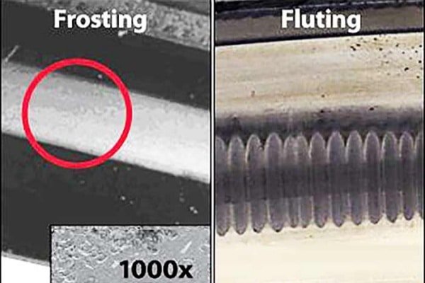
Visual Diagnostics
The hallmark of traction motor bearing failure is “washboarding” or fluting—deep, rhythmic grooves on the inner or outer rings. This damage leads to excessive noise and vibration, often triggering bogie monitoring sensors.
Bearing Insulation Options: Selecting the Right Tech
Not all insulated bearings are built for the rails.
1. Plasma-Sprayed Coatings (e.g., INSOCOAT)
Technology: A ceramic layer (aluminum oxide) plasma-sprayed onto the outer or inner ring.
Pros: The industry standard for decades; cost-effective; effective against circulating currents.
Cons: The coating is brittle and can be damaged during press-fitting; it has finite capacitance, allowing some very high-frequency current to pass.
2. Hybrid Ceramic Bearings (The Future Standard)
Technology: Steel rings with Silicon Nitride (Si3N4) rolling elements.
Pros: Infinite DC electrical resistance; significantly lower centrifugal force at high RPMs; superior durability in grease-starved conditions.
Application: Increasingly mandatory for motors driven by Silicon Carbide (SiC) inverters due to their extreme switching speeds.
3. Resin-Coated Bearings (PPS)
Technology: Glass-fiber reinforced Polyphenylene Sulfide (PPS) resin injection-molded onto the outer ring.
Application: Specialized solution used in some Japanese Shinkansen and metro applications for robust insulation.
Standards & Compliance (IEC / IEEE)
Engineering decisions must be backed by standards.
IEC 60349-2
This standard specifically covers “Electric traction – Rotating electrical machines for rail and road vehicles – Part 2: Electronic converter-fed alternating current motors.” It mandates rigorous testing for insulation systems to withstand the high dV/dt stress of modern inverters.
NEMA MG 1 Part 31
In North America, this standard defines “Definite Purpose Inverter-Fed Polyphase Motors,” setting limits for peak voltage (1600V) and rise times, guiding the insulation requirements for traction motor windings and bearings.
Maintenance & Life Extension Strategies
Keeping the insulation intact is a lifelong task.
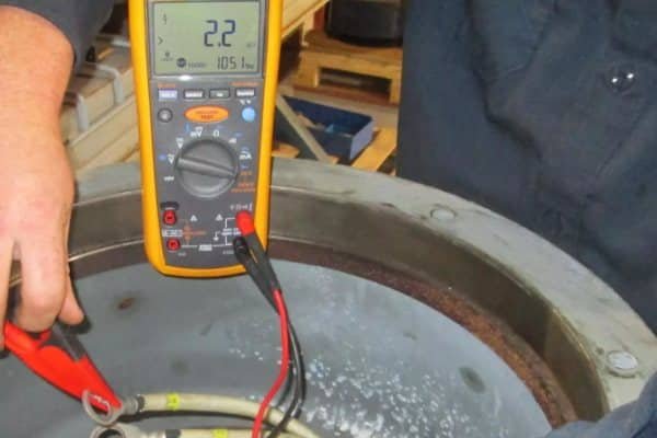
Megger Testing
Regularly test the insulation resistance of the bearing using a Megohmmeter (typically at 500V DC). A healthy coated bearing should show >50 MΩ resistance. A drop in resistance indicates coating damage or conductive contamination (bridge).
Cleaning Intervals
Railway environments are dirty. Brake dust (conductive iron powder) and carbon brush dust can accumulate around the bearing seal, creating a conductive bridge that bypasses the insulation. Regular cleaning of the bearing shield area is vital.
Frequently Asked Questions (FAQ)
Why do traction motors need insulated bearings on both ends?
Due to the high magnitude of common mode voltage in traction inverters, simply breaking the loop at one end is often insufficient. Insulating both the Drive End (DE) and Non-Drive End (NDE) provides the highest level of protection against all current types.
Can I replace a standard bearing with an insulated one in a locomotive?
Yes, provided the dimensions match. However, you must ensure the housing fit is correct and that no conductive grease or debris bridges the insulation during installation.
What is the minimum insulation resistance for a traction motor bearing?
While manufacturers specify values (often >50 MΩ or >100 MΩ when new), in service, a value dropping below 1-5 MΩ is a red flag indicating the insulation has been compromised.