
In modern industrial facilities, motor reliability is paramount. Yet, an invisible force—motor shaft voltage—continues to be a leading cause of premature bearing failure. As the industry shifts heavily towards Variable Frequency Drives (VFDs) for energy efficiency, the incidence of shaft voltage-related issues has spiked. Understanding how this voltage is generated, measuring it accurately, and implementing the right grounding strategies are essential skills for today’s reliability engineers.
In this comprehensive guide, you will learn:
- The physics of parasitic capacitance and how motors accumulate charge.
- The three primary sources of shaft voltage, including VFD common mode voltage.
- Industry standards for safe voltage limits (NEMA MG1 guidelines).
- Why standard multimeters cannot accurately measure these high-frequency signals.
- A comparison of mitigation solutions: Shaft Grounding Rings vs. Insulated Bearings.
Let’s begin by demystifying how a steel shaft becomes an electrical conductor of destruction.
What is Motor Shaft Voltage? (The Basics)
Motor shaft voltage is the electrical potential difference between the motor’s rotor shaft and its grounded frame. In a perfectly ideal motor, this should be zero. However, in reality, various electrical and magnetic mechanisms induce a voltage on the spinning rotor.
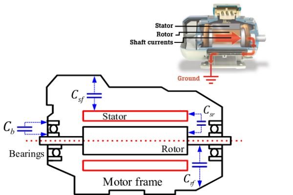
The Concept of “Parasitic Capacitance”
To understand shaft voltage, you must view the motor as a capacitor. The stator windings act as one plate, the rotor acts as the other, and the air gap between them is the dielectric. Stray capacitance (parasitic capacitance) naturally exists here. When high-frequency power is applied to the stator, voltage is capacitively coupled onto the rotor shaft. Since the rotor is supported by lubricated bearings (which are insulators), the charge is trapped on the shaft.
The “Breakdown” Moment
The voltage builds up until it exceeds the dielectric strength of the grease film in the bearings (typically 10-30 Volts). Once this limit is reached, the energy discharges instantaneously through the bearing to the ground. This discharge is the “spark” that causes pitting and fluting damage.
The 3 Main Sources of Shaft Voltage
Identifying the source is critical for choosing the right solution.
1. VFD Induced (Common Mode Voltage)
This is the most common cause in modern industry. VFDs use Pulse Width Modulation (PWM) to control speed. The rapid switching of the drive’s transistors creates “Common Mode Voltage”—a non-zero voltage that does not sum to zero. This high-frequency noise couples capacitively to the shaft.
2. Magnetic Dissymmetry (Frame Imbalance)
Often found in large frame motors or motors with manufacturing imperfections. Asymmetries in the stator’s magnetic field induce a low-frequency AC voltage along the shaft. This creates a circulating current loop.
3. Static Electricity (External)
External components like belt drives or conveyors can generate significant static electricity. This charge can travel down the shaft and discharge through the motor bearings if not properly grounded.
Damage Limits: How Much Voltage is Too Much?
Engineers often ask: “What is the safe limit?”
NEMA MG1 Standards
According to NEMA MG1 Part 31, shaft voltages should generally be kept below 10 to 20 Volts peak-to-peak. However, many reliability experts suggest a stricter limit of <5 Volts for maximum safety, especially with modern synthetic greases.
Factors Influencing the Limit
The “danger threshold” depends on the grease film thickness. A motor running at low speed or high temperature has a thinner oil film, making it susceptible to arcing at lower voltages.
How to Measure Shaft Voltage Correctly
A common mistake is using a standard Digital Multimeter (DMM). A DMM averages the signal and will show near-zero volts even when dangerous spikes exist.
Using an Oscilloscope
To see the true picture, you must use an oscilloscope with a bandwidth of at least 100 MHz. The high-frequency pulses from a VFD occur in microseconds.
The Carbon Brush Probe
You cannot measure a spinning shaft with a standard alligator clip. You need a Shaft Voltage Probe equipped with a conductive carbon brush or microfiber tip. This tip rides gently on the rotating shaft end to pick up the voltage signal.
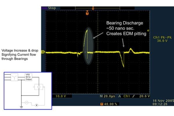
Interpreting the Waveform
On the scope screen, look for a “sawtooth” pattern followed by a sharp vertical drop. The vertical line indicates the moment of discharge (arcing) where the voltage instantly drops to zero as it shorts through the bearing.
Mitigation Solutions: Grounding and Insulation
Once high voltage is confirmed, you must mitigate it.
Shaft Grounding Rings (SGR)
Best for: VFD-driven low voltage motors (under 100 HP).
SGRs use millions of conductive microfibers to create a low-impedance path from the shaft to the frame. This bleeds off the voltage continuously, preventing it from building up to arcing levels.
Insulated Bearings (Ceramic/Hybrid)
Best for: Large motors (>100 HP) or critical applications.
Hybrid bearings use ceramic balls that are non-conductive. They act as a firewall, stopping current from flowing through the bearing regardless of the shaft voltage level.
High-Frequency Bonding Straps
Connecting the motor frame to the building ground with a flat, braided strap is crucial. Round wires have high impedance at high frequencies due to the “skin effect,” rendering them ineffective for VFD noise.
Frequently Asked Questions (FAQ)
Can shaft voltage occur in non-VFD motors?
Yes, primarily due to magnetic dissymmetry or external static from belts. However, the intensity and frequency of damage are significantly lower compared to VFD applications.
Do I need grounding rings on both ends of the motor?
Typically, no. A single grounding ring on either the drive end or non-drive end is sufficient to bleed capacitive voltage. However, for large motors with circulating currents, you need an insulated bearing on one end and a grounding ring on the other.
What is the difference between shaft voltage and bearing current?
Shaft voltage is the potential (pressure) building up on the rotor. Bearing current is the actual flow of electrons that occurs when that voltage discharges. Voltage is the cause; current is the damaging result.