
What Is an Insulation Layer on a Bearing?
An insulation layer on a bearing is a specialized non-conductive coating or structural barrier designed to prevent damaging electrical currents from passing through the rolling elements. In modern electric motors—especially those powered by variable frequency drives (VFDs)—electrically induced bearing currents can cause pitting, frosting, and fluting, ultimately shortening motor life. Insulation layers provide a highly effective method of blocking these currents, improving reliability and extending service life in demanding industrial applications.
In this complete guide, you will learn:
- The purpose of insulation layers and how they protect bearings from EDM damage
- Common insulation materials such as ceramic oxides and engineered polymers
- How insulation layers are structured, applied, and quality-controlled
- Electrical and mechanical performance characteristics engineers rely on
- Where insulated bearings are used and when they provide the most value
- Key FAQs that help engineers distinguish insulation choices and testing methods
Let’s begin by defining what a bearing insulation layer actually is and why it plays such a vital role in electrically stressed motor environments.
What Is a Bearing Insulation Layer?
Purpose of insulation in preventing electrical current flow
The primary purpose of an insulation layer is to create a dielectric barrier between the bearing rings and the motor frame. This barrier prevents shaft voltage and circulating currents from discharging through the rolling contacts—eliminating the electrical arcing that leads to EDM-related bearing damage.
How insulation stops EDM, pitting, and bearing fluting
When the insulation layer blocks conductive paths, harmful electrical discharge is prevented. This eliminates micro-arcing responsible for pitting, the widespread micro-damage known as frosting, and the patterned groove formation typical of electrical fluting.
Where insulation is applied (outer ring, inner ring, housing, or rolling elements)
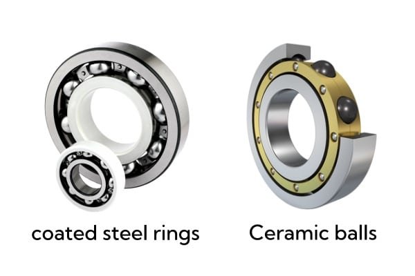
Most insulated bearings apply ceramic coatings to the outer ring, while some designs insulate the inner ring or bearing housings. Hybrid bearings achieve insulation through ceramic rolling elements instead of coated rings.
Insulation layer vs hybrid ceramic design (fundamental differences)
Insulated bearings use a non-conductive coating on steel rings, while hybrid bearings eliminate electrical conductivity by replacing steel balls with silicon nitride ceramic balls. Hybrid bearings also reduce friction and heat, but at a higher cost and with different mechanical characteristics.
Materials Used for Insulation Layers
Ceramic coatings (Al₂O₃, zirconia/zrO₂, TiO₂ variants)
Aluminum oxide (Al₂O₃) is the industry standard for bearing insulation layers due to its excellent dielectric strength, hardness, and chemical resistance. Zirconia and titanium oxide variants are used for enhanced toughness or specialized environments.
Polymer-based insulating layers (PPS, PEEK)
High-performance polymers such as PPS and PEEK are used where thinner coatings, lower thermal mass, or corrosion resistance are required. They are typically found in smaller bearings or compact applications.
Plasma-sprayed oxide coatings vs thin-film engineered coatings
Most industrial insulated bearings rely on plasma-sprayed ceramic coatings for ruggedness and high dielectric strength. For precision applications, thin-film engineered coatings offer smoother surfaces and tighter tolerances.
Material properties—dielectric strength, hardness, thermal stability
The performance of an insulation layer depends on high dielectric strength (typically 500–2000 V), excellent hardness to resist wear, stable behavior under high temperatures, and resistance to humidity or contamination.
Why ceramic coatings dominate VFD & high-voltage applications
Ceramic coatings provide the best combination of electrical resistance, durability, and cost-effectiveness. They withstand the high-frequency stresses generated by modern PWM inverters better than polymer alternatives.
How the Insulation Layer Is Structured
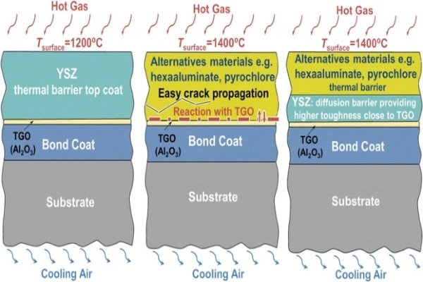
Multi-layer coating stack: bond coat → ceramic layer → sealing layer
Industrial coating systems use a multi-layer design: a bond coat to ensure adhesion, a thick ceramic insulation layer for dielectric protection, and a sealing layer to reduce porosity and protect against moisture.
Insulation thickness ranges (100–300 µm typical)
Most insulated bearings feature coating thicknesses between 100 and 300 microns. Thicker coatings offer greater voltage resistance but require precise process control to maintain dimensional accuracy.
Surface preparation, grit blasting, and adhesion control
Before coating, the steel surface is grit-blasted to increase surface roughness and ensure strong mechanical bonding. Adhesion quality directly influences coating durability under vibration and thermal cycling.
Microstructure characteristics (porosity, density, crack resistance)
The microstructure of the ceramic layer determines its electrical and mechanical performance. Controlled porosity prevents conductive bridges, while high density and crack resistance ensure long-term reliability.
Differences between insulated rings and hybrid ceramic bearings
Insulated rings retain steel races with a dielectric coating, while hybrid bearings use ceramic balls to eliminate conductive contact. Both reduce electrical stress, but hybrid bearings also reduce mass and friction for high-speed operation.
Electrical Performance of Insulated Bearings
Breakdown voltage & dielectric strength requirements
An insulation layer must withstand expected shaft voltages without failure. Typical breakdown voltages range from 500 V for thin coatings to 2000 V or more for heavy-duty industrial designs.
Resistance to high-frequency discharge from PWM inverters
High-frequency PWM switching can generate steep voltage rise times (dv/dt). Ceramic insulation provides stable dielectric behavior under these conditions and prevents capacitive discharge through the bearings.
Insulation resistance under varying humidity & contamination
Humidity and conductive contaminants reduce dielectric resistance. Sealed ceramic coatings maintain performance even in wet or corrosive environments, making them suitable for HVAC, mining, and outdoor applications.
Heat dissipation behavior of ceramic coatings
Ceramics conduct heat differently than steel but provide adequate dissipation for bearing operation. Proper lubrication ensures minimal thermal stress across the insulation interface.
Typical performance benchmarks (OEM standards, insulation class expectations)
OEM specifications often require insulated bearings for motors above 400 V or for inverter-duty service. Dielectric strength, dimensional tolerances, and coating adhesion must meet strict industry standards.
Mechanical & Reliability Considerations
Wear resistance and surface hardness improvements
Ceramic insulation layers add hardness to the raceway surface, improving wear resistance and extending mechanical life in addition to electrical protection.
Coating durability under vibration and thermal cycling
Properly bonded ceramic coatings withstand motor vibration, load variation, and cyclic thermal expansion without cracking or delaminating.
Interaction with lubricants and sealing systems
Insulation layers must remain compatible with greases and oils. Modern coatings maintain stable surfaces that prevent lubricant absorption or chemical reactions.
How the insulation layer affects bearing fatigue life
By eliminating electrically induced micro-cracking and lubrication breakdown, insulated bearings reduce surface fatigue and extend bearing life significantly compared to standard bearings.
Applications Where Insulation Layers Are Critical
VFD motors, inverter-duty motors, and long cable installations
These systems face high common-mode voltage and shaft voltage, making insulated bearings essential for reliability and lifespan.
High-voltage industrial motors
Motors operating above 400 V or in high-frequency switching environments require insulation to prevent circulating current loops through the bearings.
Mining, oil & gas, paper mills, HVAC, wind turbines
Industries with harsh environments or continuous operation benefit greatly from insulated bearings due to their resistance to electrical and environmental stress.
When to choose insulated bearings vs hybrid ceramic bearings
Insulated bearings are ideal for most general industrial applications. Hybrid ceramic bearings are recommended for high-speed, high-temperature, or extremely high-frequency electrical environments.
Frequently Asked Questions (FAQ)
How thick is a bearing insulation layer?
Typical insulation thickness ranges from 100–300 µm, depending on OEM design and voltage requirements.
What materials offer the highest dielectric strength?
Aluminum oxide (Al₂O₃) provides the highest balance of dielectric strength, durability, and cost efficiency. Zirconia and engineered polymers are used for specialized needs.
Is ceramic coating better than hybrid ceramic balls?
Not necessarily—ceramic coatings are ideal for cost-effective electrical isolation, while hybrid bearings provide the highest electrical insulation and mechanical performance at a higher cost.
Can the insulation layer wear off over time?
High-quality ceramic coatings are extremely durable. However, contamination, improper handling, or extreme vibration can damage coatings if installation practices are poor.
How do engineers test insulation performance (hipot, dielectric test)?
Common tests include hipot testing, insulation resistance measurement, and dielectric strength verification to ensure the bearing meets voltage withstand requirements.