
In the wind energy sector, reliability is currency. The cost of a simple bearing failure in a wind turbine generator (WTG) is amplified exponentially by the logistics of “uptower” repairs—especially for offshore installations where vessel deployment can cost hundreds of thousands of dollars. As turbine capacities grow into the multi-megawatt range, electrical bearing damage has emerged as a leading cause of generator downtime. Specifically, high-frequency circulating currents and the mysterious phenomenon of White Etching Cracks (WEC) threaten the viability of long-term operations.
In this energy sector guide, you will examine:
- The unique electrical stresses placed on wind generator bearings by grid-side converters.
- The link between electrical current leakage and White Etching Cracks (WEC).
- A technical comparison of Plasma-Coated vs. Hybrid Ceramic bearings for MW-class turbines.
- Why insulating the Non-Drive End (NDE) is the standard defense against circulating currents.
- The ROI of premium bearings: calculating savings against crane and vessel costs.
Let’s analyze how advanced bearing technology is keeping the blades turning.
The Unique Challenge of Wind Turbine Generators
Wind turbines are not just big fans; they are complex power plants. The use of full-scale frequency converters creates a harsh electrical environment for the generator bearings.
The Cost of Uptower Repairs
Unlike a factory motor that can be swapped with a forklift, a wind generator bearing failure requires a specialized crane or, for offshore sites, a jack-up vessel. The “cost of failure” is not the $1,000 bearing; it is the $150,000+ logistical operation and weeks of lost production.
Why Wind Generators have High-Frequency Circulating Currents
Due to the large physical size of MW-class generator stators, magnetic asymmetries are unavoidable. This creates a high-frequency voltage potential between the shaft ends. This voltage drives a circulating current loop: flowing from the shaft, through one bearing, through the housing, and back through the other bearing. This loop must be physically broken to prevent damage.
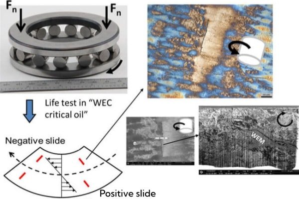
The Link to White Etching Cracks (WEC)
WEC is a premature failure mode characterized by the formation of white-appearing microstructures below the raceway surface, leading to rapid spalling. While the exact root cause is debated, strong evidence suggests that electrical current leakage, combined with mechanical stress, accelerates hydrogen embrittlement in the steel, triggering WEC. Electrical isolation is seen as a key preventive measure.
Technical Solutions: Choosing the Right Insulation
Two primary technologies dominate the wind market. The choice depends on the specific failure mode and budget.
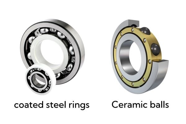
1. Plasma-Coated Bearings (e.g., INSOCOAT)
Technology: A standard steel bearing with a thin layer of aluminum oxide spray-coated onto the outer ring.
Best For: Preventing circulating currents in the stator housing.
Limitation: The coating acts as a weak capacitor. At the very high switching frequencies of modern SiC (Silicon Carbide) converters, some high-frequency noise can still couple through the coating.
2. Hybrid Ceramic Bearings (The Premium Standard)
Technology: Steel rings with Silicon Nitride (ceramic) rolling elements.
Best For: Total electrical isolation and preventing adhesive wear.
Wind-Specific Benefit: Turbines often sit idle during low wind. Steel bearings can suffer from “False Brinelling” (vibration marks) during these standstill periods. Ceramic balls are lighter and do not cold-weld to the race, making them immune to this specific standstill damage.
Strategic Installation: Drive End (DE) vs. Non-Drive End (NDE)
Where you install the insulation matters as much as the bearing type.
Insulating the NDE (Standard Practice)
To stop the circulating current loop, you only need to break the circuit at one point. The industry standard is to install an insulated bearing on the Non-Drive End (NDE). This is often cheaper and easier to service than the highly loaded Drive End (DE).
When to Insulate Both Ends
In sites with severe electrical noise or grounding issues, “Common Mode Voltage” may be high enough to cause EDM discharge at both bearings independently. In these cases, installing hybrid bearings on both the DE and NDE is required for full protection.
The “Belt and Suspenders” Strategy
Many operators now specify an insulated bearing on the NDE (to stop the loop) AND a Shaft Grounding Ring on the DE (to bleed off rotor voltage). This dual approach covers both failure mechanisms.
Economic Analysis: ROI of Upgrading Bearings
Is a $2,000 hybrid bearing worth it compared to a $500 steel one?
The “Crane Cost” Equation
If a hybrid bearing extends the generator life from 5 years to 10 years, it eliminates one entire “major component exchange” cycle. For an onshore turbine, this saves ~$50,000 in crane and labor costs. For offshore, the savings can exceed $500,000. The ROI is immediate.
Extending Grease Life
Hybrid bearings run cooler because ceramic has lower friction. Cooler running temperatures reduce the oxidation rate of the grease, allowing for longer automatic lubrication intervals. This means fewer technician climbs for maintenance.
Frequently Asked Questions (FAQ)
Can insulated bearings prevent White Etching Cracks (WEC)?
They are a strong mitigation strategy. By blocking current passage, insulated bearings remove one of the primary drivers (electrical stress) believed to contribute to hydrogen embrittlement and WEC formation.
Should I retrofit my older wind turbine with hybrid bearings?
Yes. If your fleet is experiencing generator bearing failures, upgrading to hybrid bearings during the repair is a proven life-extension strategy, especially for turbines out of warranty.
What is the lifespan difference between steel and ceramic bearings in wind applications?
In ideal mechanical conditions, both last long. However, in the presence of electrical currents, a steel bearing may fail in 6-18 months, whereas a hybrid ceramic bearing is immune to electrical wear and can last the full 20-year design life of the turbine.